

How to wire pcb mono input jack? Level up your audio game with this super-detailed guide! From basic setups to pro-level configurations, we’ll walk you through everything you need to know about connecting mono input jacks to your PCBs. Get ready to conquer the world of soldering and sound!
This guide dives deep into the world of mono input jacks, explaining their function on PCBs, common types, and the importance of proper wiring for optimal audio performance. We’ll cover everything from the essential components and tools to detailed wiring procedures and crucial PCB layout considerations. Plus, we’ll equip you with the troubleshooting skills to tackle any audio hiccups along the way.
So grab your soldering iron and let’s get wired!
Introduction to Mono Input Jacks on PCBs
Mono input jacks are essential components in electronic projects, providing a crucial interface for connecting audio sources to your circuit. They enable the transmission of audio signals from devices like microphones, instruments, or other audio sources to your circuit’s input stage. Proper understanding and correct wiring of these jacks are paramount for achieving optimal audio quality and preventing signal degradation.These jacks, often found on various PCBs, serve as the connection point for analog audio signals.
They translate the mechanical movement or electrical signals from an external device into an electrical signal that can be processed by your circuit. Careful attention to wiring details and the specific jack type is vital to ensure the audio signal is transmitted faithfully.
Common Types of Mono Input Jacks
Different mono input jacks are designed for various applications and offer varying levels of functionality. Understanding these differences helps in selecting the appropriate jack for your project. The most common types include the 1/4″ TS jack, which is prevalent in musical instrument applications and audio equipment. Other types may include specialized connectors for specific tasks.
Mono Input Jack Pinouts and Applications
| Jack Type | Pinouts | Typical Applications | Image Description |
|---|---|---|---|
| 1/4″ TS (Tip-Sleeve) | Tip (signal), Sleeve (ground) | Musical instruments, microphones, and general audio input applications. A common choice for guitar pickups and microphone inputs due to its robustness and widespread use. | A 1/4-inch TS jack is soldered to a PCB. The tip of the jack is connected to the circuit’s input signal line, while the sleeve is connected to the ground. The connection points are clearly visible on the PCB, showcasing the straightforward nature of the wiring. |
| 1/8″ TS (Stereo Mini Jack – Mono Mode) | Tip (signal), Sleeve (ground) | Portable audio devices, computer audio interfaces, and applications where a smaller jack size is desirable. | A 1/8-inch TS jack is soldered to a PCB, with the tip connected to the circuit’s input signal and the sleeve to the ground. The compact design of the jack is highlighted in the image. |
| RCA Jack | Center (signal), Outer (ground) | Consumer audio equipment, home theater systems, and video signals (although primarily used for video, the audio component is compatible with mono signals). | An RCA jack is soldered to a PCB. The center pin is the signal, and the outer ring is the ground connection. The image displays the physical configuration of the jack and its connection to the PCB tracks. |
Importance of Correct Wiring
Correct wiring for mono input jacks is critical for ensuring a clear and undistorted audio signal. Improper connections can lead to noise, signal loss, or even damage to your circuit. A well-wired connection provides the optimal path for the audio signal to flow, ensuring high-quality sound. Carefully adhering to the pinout diagrams is essential for successful wiring.
Components and Tools Needed
Crafting a robust and reliable mono input jack connection on a PCB necessitates careful selection of components and appropriate tools. This meticulous process ensures a seamless audio signal path, critical for any electronic project involving sound input. Properly chosen components and skillfully executed wiring contribute to a professional-grade audio experience.
Essential Components
Choosing the right components is fundamental to achieving a stable and high-quality audio input. A well-selected mono input jack, along with matching wires and solder, are crucial for successful wiring. These components, when combined correctly, establish a robust connection for signal transmission.
- Mono Input Jack: A crucial component, the mono input jack provides the physical connection point for audio signals. Selecting the appropriate jack type (e.g., 1/4 inch, 1/8 inch) is essential, matching it to the intended application and the specific audio source. Consider factors like the expected impedance of the audio signal source when choosing the input jack.
- Solder: High-quality solder ensures a strong and reliable connection between the jack’s pins and the PCB traces. Use rosin-core solder for its flux properties, which aids in the soldering process. Ensure the solder is appropriate for the specific gauge of wire being used to prevent issues during the process.
- Wires: Properly selected wires are essential for carrying the audio signal between the input jack and the PCB. Using stranded wire is recommended for flexibility and minimizing signal degradation. Consider the gauge of the wire (e.g., 22 AWG, 24 AWG) to ensure it can handle the signal without excessive resistance.
- Insulation Tape/Heat Shrink Tubing: Proper insulation is critical for preventing short circuits and ensuring signal integrity. Insulation tape or heat shrink tubing are used to cover exposed wires, protecting them from external interference. Choose a suitable insulation material based on the operating environment of the circuit.
Essential Tools
The right tools are instrumental in achieving a precise and professional-quality connection. These tools ensure accuracy and efficiency in the wiring process.
- Soldering Iron: A soldering iron is essential for creating reliable solder joints. The wattage of the iron should be appropriate for the type of solder being used. A variable temperature setting is beneficial for fine-tuning the soldering process.
- Soldering Station: A soldering station with a temperature control provides more precise control over the soldering process, minimizing potential issues like overheating or underheating. A soldering station can improve the consistency and quality of the solder joints.
- Wire Strippers/Cutters: Proper wire preparation is crucial. Wire strippers/cutters are essential for removing the insulation from the wires and ensuring clean cuts. These tools contribute to the overall quality and reliability of the connection.
- Multimeter: A multimeter is invaluable for verifying continuity and measuring resistance across the connection. This ensures the connection is intact and functional. A multimeter allows for proper testing and troubleshooting of the circuit.
Component Selection Guidelines
Careful consideration of application requirements is key to selecting the correct components. The type of audio source, the expected signal strength, and the environmental conditions all influence component choices. Matching the input jack to the audio source is crucial for signal integrity and optimal performance.
| Component | Description | Specifications | Image Description |
|---|---|---|---|
| Mono Input Jack | Audio input jack | 1/4 inch, solder-compatible, gold-plated contacts | A clear image of a 1/4 inch mono input jack, showcasing the solder points and the gold-plated contacts. Note the pin arrangement and the physical dimensions of the jack. |
| Solder | Provides the connection between components | Rosin-core, 60/40 lead-free solder, appropriate gauge for the wire used | A close-up image of the solder, highlighting its consistency and the rosin-core. |
| Wire | Connects the input jack to the circuit | Stranded, 22 AWG, insulated, appropriate length | A length of wire, showing its stranded construction and insulation. |
| Insulation Tape | Protects exposed wires | Heat-resistant, appropriate color for visibility | A roll of insulation tape, highlighting its texture and adhesive properties. |
Wiring Procedures for Different Types
Embarking on the exciting journey of connecting a mono input jack to your PCB is a rewarding experience. This process, though seemingly straightforward, requires precision and understanding. Mastering the correct wiring procedures ensures optimal audio performance and avoids potential issues. This section will guide you through the various wiring methods, highlighting important considerations for different types of jacks and PCB layouts.A well-executed wiring procedure not only guarantees functionality but also contributes to the overall quality and reliability of your project.
Attention to detail in this step will prevent frustrating troubleshooting later on. Let’s dive into the specifics of wiring procedures, exploring the different approaches and addressing potential challenges.
Standard Mono Input Jack Wiring
Understanding the fundamental wiring procedure for a standard mono input jack is crucial for any electronics enthusiast. This involves connecting the tip, sleeve, and ring to the appropriate signal lines on your PCB. A meticulous approach is key to success.
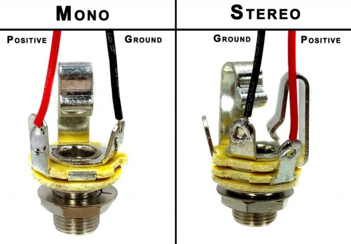
- Identify the tip, sleeve, and ring terminals on the mono input jack. The tip typically carries the audio signal, the sleeve is the ground connection, and the ring is often unused.
- Locate the corresponding signal and ground lines on your PCB. Refer to your circuit diagram for accurate pinouts.
- Use appropriate solder to connect the tip of the jack to the audio signal line on the PCB. Ensure a strong, reliable solder joint.
- Connect the sleeve of the jack to the ground line on the PCB, creating a stable ground connection. A solid solder connection is critical for preventing signal interference.
- If the ring terminal is present, ensure it is either soldered to the PCB’s ground or left unconnected. This depends on the specific circuit design. Follow your circuit diagram.
- Test the connection by applying a signal source to the input jack. Observe the output for a clear and consistent signal. Pay close attention to any distortion or unwanted noises.
Wiring Procedures for Different Types of Mono Input Jacks
Different mono input jacks might have slightly varied pinouts. Understanding these variations is crucial for successful wiring. This section details how to handle different types of jacks.
- Some mono input jacks may have a separate ground connection. In these cases, ensure that the corresponding ground line on the PCB is connected to the jack’s ground terminal. The correct identification and connection of the ground terminal are essential for avoiding short circuits.
- Other types might have an additional ring terminal. This additional terminal may be used for specific functions, such as switching or additional signal conditioning. Always refer to the specific jack’s datasheet or circuit diagram.
- Always ensure that the jack is correctly oriented on the PCB. The orientation of the jack will affect the correct wiring connections. This is a crucial step in preventing errors.
Comparison of Wiring Methods for Different PCB Layouts
Different PCB layouts can influence the optimal wiring methods. This section highlights how different approaches cater to different PCB structures.
- A through-hole PCB layout may necessitate longer solder connections. Careful attention to solder joints and avoiding excess solder is essential to maintain circuit integrity.
- Surface-mount PCBs often require smaller solder joints. Use the appropriate soldering tools and techniques to create reliable connections with minimal excess solder.
- Consider the proximity of components. Strategic placement of components and input jacks minimizes the risk of short circuits and improves signal integrity.
Soldering Techniques for PCB Wiring
Various soldering techniques exist, each with its own advantages and considerations. Choosing the right method is crucial for successful wiring.
- Using a soldering iron with appropriate temperature settings is essential. Excessive heat can damage components, while insufficient heat results in weak solder joints.
- Ensure proper solder application. Too much solder can create bridges and short circuits, while insufficient solder results in weak joints.
- Practice appropriate soldering techniques. Practice on scrap PCBs or components before working on your main project to ensure proficiency.
Potential Issues and Troubleshooting Steps
Troubleshooting wiring issues is a crucial skill for any electronics enthusiast. This section details common problems and solutions.
- Common problems include solder bridges, weak solder joints, and incorrect wiring. Examine all connections for these issues.
- To address solder bridges, carefully remove the excess solder using a solder sucker. Be cautious to avoid damaging the PCB or components.
- If the connection is weak, reheat the joint with a soldering iron and reapply solder. Ensure the joint is properly formed.
- Double-check the wiring diagram and ensure that all connections are correct. A careful review is often the first step in identifying the root cause.
Circuit Diagrams and Schematics: How To Wire Pcb Mono Input Jack
Unlocking the potential of your mono input jack requires a deep understanding of its circuit diagrams and schematics. These visual representations act as blueprints, guiding you through the intricate pathways of audio signals as they travel from the jack to your audio processing components. By understanding these diagrams, you gain the ability to customize and optimize your audio circuits for specific needs and applications.A thorough examination of circuit diagrams and schematics allows you to analyze the flow of audio signals, identify potential signal degradation points, and implement crucial protective measures.
This knowledge empowers you to create robust and reliable audio systems that deliver high-quality sound.
Example Mono Input Circuits
Various circuit configurations can be employed for connecting a mono input jack to an amplifier. Each configuration presents a unique set of advantages and disadvantages, making it essential to choose the appropriate circuit based on your specific application requirements.
- Simple Input Circuit: This circuit provides a direct connection between the input jack and the amplifier’s input. It’s the simplest and most cost-effective option, but it lacks inherent protection against overloads and other potential issues. This straightforward approach is often sufficient for low-level audio applications, but robust protection measures are crucial for applications with a higher potential for signal surges.
- Buffered Input Circuit: This circuit utilizes a buffer amplifier to isolate the input jack from the amplifier’s input. This isolation enhances signal quality and prevents the amplifier’s input characteristics from affecting the input jack. This buffering feature enhances the stability and resilience of the circuit by mitigating the effects of variations in the amplifier’s input impedance.
- Input Circuit with Protection: This circuit includes diodes or other components to protect the amplifier from overvoltages or short circuits. This extra layer of protection safeguards the delicate components of the amplifier and ensures the longevity of the audio system. These protective measures are paramount in high-power audio applications, where there is a higher risk of damage from unexpected surges in signal strength.
Comparison of Different Circuit Diagrams
The following table summarizes the key characteristics of different mono input jack circuit diagrams.
| Circuit Diagram | Description | Advantages | Disadvantages |
|---|---|---|---|
| Simple Input Circuit | Direct connection from the input jack to the amplifier’s input. | Easy to implement, low cost. | Limited protection against overloads and short circuits. |
| Buffered Input Circuit | Utilizes a buffer amplifier to isolate the input jack from the amplifier’s input. | Improved signal quality, enhanced stability, and reduced susceptibility to variations in the amplifier’s input impedance. | Increased complexity and cost compared to the simple input circuit. |
| Input Circuit with Protection | Includes diodes or other components to protect the amplifier from overvoltages and short circuits. | Enhanced protection for the amplifier, ensuring system longevity. | Increased complexity and potential for slight signal attenuation. |
Schematics for Different Audio Applications
The specific schematic for your audio application will depend on factors like the required signal levels, the type of amplifier, and any necessary protection measures.
Illustrative examples of schematics for different audio applications are provided below:
- Mic Preamplifier Circuit: This schematic incorporates a microphone preamplifier to boost the low-level signal from a microphone. The preamplifier provides a suitable signal level for the input stage of an amplifier or recording device. This allows the recording device to capture the subtle nuances of the microphone signal, resulting in a high-fidelity recording.
- Line-Level Input Circuit: This schematic handles line-level signals from an audio source. The circuit provides a direct connection to the amplifier input, suitable for audio signals from devices such as CD players, cassette players, or other audio playback devices. This direct approach is crucial for maintaining the integrity of the audio signal and avoiding signal loss.
Component Roles in the Circuit
The roles of different components in these circuits are critical to understanding their functionality. Resistors, capacitors, and diodes each contribute specific tasks, like impedance matching, filtering unwanted signals, and protecting the circuit from damage. A deep understanding of these components allows for informed modifications to the circuit, allowing for optimization for particular applications.
PCB Layout Considerations


Crafting a high-quality audio circuit necessitates meticulous attention to detail, particularly in the PCB layout for the mono input jack. Proper placement and routing of traces directly impact signal integrity, influencing the overall performance and reliability of the audio system. Careful consideration of these factors ensures a robust and clear audio path.The layout of the input jack on the PCB should be designed with the goal of minimizing signal degradation, noise pickup, and impedance mismatches.
The physical arrangement of components and traces significantly impacts the circuit’s ability to faithfully transmit audio signals. This section delves into crucial aspects of PCB layout for mono input jacks, emphasizing techniques for achieving optimal signal integrity.
Trace Width and Length
Trace width and length are critical parameters affecting signal integrity. Wider traces provide lower resistance and capacitance, facilitating faster signal propagation and reducing signal loss. Conversely, excessively wide traces can lead to increased parasitic capacitance and inductance, hindering signal quality. Likewise, longer traces can introduce significant signal delay and attenuation. Maintaining an appropriate balance between trace width and length is vital for optimal signal transmission.
Ground Plane Considerations
Implementing a robust ground plane is essential for minimizing noise. A well-defined ground plane provides a low-impedance path for current, effectively suppressing noise and crosstalk. A continuous ground plane under the critical traces and components is crucial. This plane should be connected to the ground pins of the input jack and the circuit’s ground point.
Component Placement
Strategic component placement is equally important. Components should be positioned to minimize unwanted coupling and electromagnetic interference. Components generating high frequencies or high currents should be placed away from sensitive circuits or components. Keeping high-frequency components, such as capacitors, away from the input jack and audio signal paths, minimizes the chance of signal degradation and noise.
Routing Considerations
Careful routing of traces is crucial to avoid signal reflections and noise. Traces should be routed in a manner that minimizes sharp bends and discontinuities. Sharp bends can introduce significant reflections, distorting the audio signal. Straight, smooth routing paths minimize these effects. Routing traces far from high-frequency components further minimizes interference.
Best Practices for PCB Layout, How to wire pcb mono input jack
| Layout Consideration | Explanation | Impact on Signal Integrity | Example Image |
|---|---|---|---|
| Trace Width | The width of the traces connecting the jack to the circuit. Wider traces offer lower resistance and capacitance. | Affects signal speed and noise. Wider traces reduce signal loss and improve speed. | An image depicting a magnified view of a trace with an appropriate width, showing a smooth, uniform cross-section. |
| Trace Length | The length of the traces connecting the jack to the circuit. | Affects signal delay and attenuation. Shorter traces minimize signal degradation. | A schematic showing different trace lengths and their impact on signal timing. |
| Ground Plane | A continuous ground plane under the critical traces and components. | Minimizes noise and crosstalk by providing a low-impedance path for current. | A schematic diagram illustrating a well-defined ground plane connecting to the input jack’s ground pin and the circuit’s ground point. |
| Component Placement | Strategic positioning of components to minimize unwanted coupling and electromagnetic interference. | Reduces noise and signal distortion by separating high-frequency and high-current components from sensitive circuits. | A layout diagram highlighting the positioning of components, with high-frequency components kept away from the input jack and audio signal paths. |
| Trace Routing | Careful routing of traces to avoid signal reflections and noise. | Minimizes signal distortion by avoiding sharp bends and discontinuities. | A schematic diagram illustrating proper trace routing with smooth, straight paths and minimal bends. |
Testing and Troubleshooting
Successfully wiring your mono input jack is a significant step in creating a functional audio circuit. Now, let’s unlock the secrets to confident troubleshooting, ensuring your project performs flawlessly. A well-tested circuit is a reliable circuit, and understanding the testing process is key to a rewarding experience.Thorough testing and troubleshooting are crucial for ensuring the functionality and reliability of your wired mono input jack.
Identifying and resolving issues early saves time and frustration, ultimately leading to a more satisfying project outcome. The process of diagnosing and fixing problems is a valuable skill, applicable to many aspects of electronics and problem-solving in general.
Testing the Wired Mono Input Jack
To ensure proper functionality, the wired mono input jack must be rigorously tested. This involves verifying the signal path, confirming proper impedance matching, and detecting any potential noise or interference. Careful attention to detail during this stage will minimize issues and guarantee a smooth audio signal.
- Visual Inspection: Carefully examine the wiring connections for any loose or damaged components. Ensure all solder joints are secure and the wires are properly terminated. A well-maintained circuit is a strong and reliable circuit.
- Continuity Testing: Use a multimeter to check the continuity of the wiring. This ensures there are no breaks or shorts in the signal path. Verify the connection between the input jack’s pins and the circuit’s components.
- Signal Verification: Apply a known audio signal to the input jack and monitor the output. This helps determine if the signal is being transmitted correctly. An audio generator is essential here for precise signal testing.
Identifying and Resolving Common Wiring Issues
Common wiring issues can significantly impact the performance of the mono input jack. Identifying and resolving these issues promptly is crucial.
- Loose Connections: A loose connection can lead to intermittent signal problems or a complete lack of signal. Tightening the connections is a common solution to this issue. Regular maintenance and inspection can prevent this problem from recurring.
- Incorrect Polarity: In some cases, the wiring may have incorrect polarity. Checking and correcting this issue is crucial to the proper functionality of the circuit. This may result in an inverted or muted audio signal.
- Ground Loops: Ground loops can cause unwanted noise in the audio signal. Identifying and resolving ground loops is a critical step in achieving clean audio. Use a ground reference point and maintain proper grounding practices throughout the circuit.
Troubleshooting Signal Problems
Signal problems can manifest in various ways, from muted audio to distorted signals.
- Signal Attenuation: Signal attenuation occurs when the signal strength decreases along the transmission path. This can be due to high impedance or excessive wire length. Using high-quality components and shorter wiring runs are possible solutions.
- Signal Distortion: Distorted signals can result from insufficient signal amplification or component damage. Checking the signal strength at various points in the circuit helps identify the problem area. Ensure sufficient amplification stages if required.
- Signal Dropouts: Signal dropouts, or intermittent signal loss, can indicate a problem with the connection or the components. Verify the connections, check for loose connections, and ensure all components are in proper working order. Pay particular attention to the stability of solder joints.
Troubleshooting Noise Issues
Noise in the audio signal can be disruptive and unpleasant. Various techniques can help identify and resolve the issue.
- External Noise Sources: External sources of noise can be mitigated by shielding the circuit or using filtering techniques. Using shielded cables and grounding the circuit effectively will reduce noise.
- Ground Noise: Ground noise is a common source of interference in audio circuits. Ensuring proper grounding practices and using a ground reference point are essential steps in mitigating ground noise. Proper grounding will minimize noise and ensure the stability of the circuit.
- Improper Filtering: Insufficient filtering can allow unwanted frequencies to pass through, creating noise in the audio signal. Using appropriate filtering techniques, such as capacitors and inductors, can effectively reduce noise. Careful selection of filter components is important for effective noise reduction.
End of Discussion

Wiring a mono input jack to your PCB just got a whole lot easier! This comprehensive guide covered everything from the fundamental concepts to advanced troubleshooting. You’ve learned how to choose the right components, perform the wiring procedures, design the PCB layout, and test your work. Now you’re ready to rock your audio projects with confidence! Remember, practice makes perfect, so get soldering and unleash the sonic potential of your creations!
FAQ Summary
What kind of tools do I need for this project?
You’ll need a soldering iron, solder, wire strippers, a multimeter, and tweezers. Safety glasses are also a must!
What are some common mistakes when wiring mono input jacks?
Incorrect solder joints, wrong pin connections, and poor PCB layout are common pitfalls. Careful attention to detail is key to avoid these errors!
How do I troubleshoot if my audio isn’t working?
Start by checking the connections, then verify the components’ proper functionality using a multimeter. If the signal is weak, check the trace width and routing on your PCB. If you’re still stuck, consult online forums or communities!
What are the different types of mono input jacks?
Common types include 1/4″ TS jacks, often used for instruments and microphones. Understanding the pinouts (Tip, Ring, Sleeve) is crucial for proper wiring.