 Nimila
How to wire a 1 wire alternator – How to wire a 1-wire alternator is a crucial skill for anyone working with automotive electrical systems. This guide delves into the intricacies of single-wire alternator systems, contrasting them with traditional multi-wire designs. We’ll explore the components, wiring diagrams, troubleshooting, safety precautions, and maintenance schedules needed to ensure optimal performance and longevity.
Understanding the differences between single and multi-wire alternators is paramount. Single-wire systems, while often simpler in design, demand a meticulous approach to ensure proper functionality. This guide will break down each step of the process, from initial setup to ongoing maintenance, equipping you with the knowledge and confidence to tackle this task successfully.
Introduction to 1-Wire Alternators
One-wire alternator systems are a specialized type of electrical generation system used in various applications, particularly in situations where space constraints or cost-effectiveness are crucial factors. They differ significantly from the more common multi-wire alternator designs in their wiring configuration and internal components. This difference leads to both advantages and disadvantages that need careful consideration when choosing a system.-wire alternators use a single wire to carry both the output voltage and the control signals, unlike multi-wire systems that use separate wires for each function.
This simplification of the wiring harness can lead to significant reductions in size and weight, making them suitable for compact applications. However, the single-wire design also introduces complexities in the control and monitoring of the alternator’s output.
Fundamental Differences Between 1-Wire and Multi-Wire Alternators
The core distinction lies in the wiring scheme. Multi-wire alternators employ multiple wires, typically separating the power output from control signals. This separation enables independent monitoring and control, leading to greater flexibility and fault diagnostics. In contrast, 1-wire systems integrate both output voltage and control signals onto a single conductor. This integration simplifies the wiring but makes fault isolation and troubleshooting more complex.
Advantages of 1-Wire Alternator Systems, How to wire a 1 wire alternator
The advantages of 1-wire alternators are primarily focused on cost-effectiveness and space-saving design features.
- Reduced Wiring Complexity: A single wire significantly simplifies the wiring harness, reducing the overall weight and space requirements for installation.
- Lower Cost: The reduced number of wires and associated components typically translate to lower manufacturing costs, making them attractive for budget-conscious applications.
- Compact Design: The streamlined wiring configuration allows for a more compact alternator design, which is beneficial in applications with limited space.
Disadvantages of 1-Wire Alternator Systems
Despite the advantages, 1-wire systems have drawbacks that need careful consideration.
- Increased Fault Diagnostics Complexity: Troubleshooting issues becomes more challenging because a single wire carries both power and control signals, making it harder to isolate the source of any fault.
- Limited Control Options: The single-wire configuration might limit the range of control options available compared to multi-wire systems, impacting the precision of the alternator’s performance.
- Potential for Signal Interference: A single wire carries both output and control signals, potentially increasing susceptibility to signal interference from other components in the system.
Component Comparison
This table illustrates the differences in components between 1-wire and multi-wire alternators.
Components of a 1-Wire Alternator System
A 1-wire alternator system, unlike traditional multi-wire setups, simplifies the electrical connections to the alternator. This streamlined approach reduces the complexity of wiring and potentially lowers manufacturing costs. However, understanding the critical components and their interactions is essential for proper system design and operation.
Essential Components
The core components of a 1-wire alternator system are designed for efficient power generation and delivery. They work in concert to convert mechanical energy from the engine into electrical energy.
| Component Name | Function | Typical Specifications |
|---|---|---|
| Alternator | The heart of the system, the alternator converts mechanical rotation into electrical energy. It houses the stator windings, rotor, diodes, and voltage regulator. | Output voltage: 12-14.4V; Output current: Dependent on engine RPM and load; Mounting type: varies by application |
| Rectifier Bridge | Converts the alternating current (AC) generated by the alternator into direct current (DC). This is crucial for charging the battery and powering the vehicle’s electrical system. | Current capacity: varies based on alternator output; Voltage drop: typically minimal |
| Voltage Regulator | Maintains a stable output voltage from the alternator, regardless of changes in engine speed or load. It prevents overcharging the battery and protects the electrical system. | Input voltage range: matches the alternator output; Output voltage: maintains a consistent output voltage; Protection features: over-voltage, over-current |
| Battery | Stores the DC electrical energy generated by the alternator, providing a reserve power source for the vehicle’s electrical system when the engine is off or at low RPM. | Capacity: varies by vehicle and application; Voltage: typically 12V; Amp-hour rating: determines the amount of charge stored |
| Wiring Harness (1-Wire) | The single-wire connection carries the combined DC power output from the alternator. This wire delivers the electrical energy from the alternator to the battery. | Wire gauge: Dependent on the current capacity; Insulation: appropriate for vehicle environments; Connector type: suitable for the specific application |
Component Interaction
The components interact in a sequential manner to deliver power. The alternator, driven by the engine’s crankshaft, generates AC power. This AC power is then rectified by the bridge rectifier into DC power. The voltage regulator maintains a constant voltage level for the DC output, ensuring the battery charges correctly and that other electrical components operate within the appropriate voltage range.
The 1-wire harness carries this DC energy to the battery for storage.
The 1-wire system significantly simplifies the wiring complexity compared to conventional multi-wire systems. This simplification leads to cost savings in manufacturing and installation.
The battery, in turn, provides the necessary power to operate the vehicle’s electrical components when the engine is not running. This system ensures a reliable power source for the vehicle’s operation.
Wiring Diagrams and Procedures
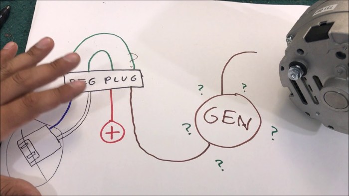
A crucial aspect of installing a 1-wire alternator system is understanding and correctly implementing the wiring diagrams. Proper wiring ensures the system functions effectively and safely, avoiding potential damage to the components and the vehicle’s electrical system. This section details various wiring scenarios and installation procedures, emphasizing safety precautions.
Wiring Diagram Examples
Different configurations may be required depending on the specific vehicle and alternator model. These diagrams illustrate the connections for various scenarios. Properly identifying and connecting the wires is paramount to the alternator’s operation and the vehicle’s electrical system.
| Scenario | Wire 1 Connection | Wire 2 Connection | Wire 3 Connection |
|---|---|---|---|
| Scenario 1: Basic System | Connect to the battery positive terminal. | Connect to the battery negative terminal. | Connect to the alternator’s field coil. |
| Scenario 2: System with External Regulator | Connect to the battery positive terminal. | Connect to the battery negative terminal. | Connect to the external regulator’s input terminal. |
| Scenario 3: System with Voltage Sensing | Connect to the battery positive terminal. | Connect to the battery negative terminal. | Connect to the voltage sensing circuit. |
Installation Procedures
The following steps detail the process for installing a 1-wire alternator, highlighting crucial safety measures. Careful adherence to these procedures is critical for a successful installation.
- Disconnect the Battery Terminals: Ensure the vehicle’s battery terminals are disconnected before any electrical work begins. This prevents short circuits and electrical shocks. This critical step prevents accidental electrical shocks and ensures the safety of the installer.
- Identify the Wires: Carefully examine the wires connected to the alternator and the vehicle’s electrical system. Proper identification of each wire is essential for successful connection. Labeling wires with electrical tape with a marker to correspond to the wiring diagram is highly recommended.
- Connect Wire 1: Connect the first wire (typically the positive wire) to the positive terminal of the battery. Use the appropriate size wire and ensure a secure connection to prevent any electrical issues. Use appropriate clamps or connectors to ensure a secure and reliable connection.
- Connect Wire 2: Connect the second wire (typically the negative wire) to the negative terminal of the battery. This completes the ground connection. Again, use appropriate clamps and connectors for a secure connection.
- Connect Wire 3: Connect the third wire (typically the field coil wire) to the appropriate terminal on the alternator. Verify the correct connection using the wiring diagram as a guide. This is often the most critical step to ensure the alternator functions properly.
- Reconnect Battery Terminals: Reconnect the battery terminals in the reverse order they were disconnected. Ensure the connections are secure and that no wires are touching each other. This is a final critical step, and ensuring a tight connection is vital to prevent any electrical problems.
- Test the System: Start the vehicle and monitor the alternator’s output. Verify the voltage output is within the specified range for the vehicle. This step ensures the alternator is functioning as expected and the vehicle’s electrical system is operating properly.
Safety Precautions
Adhering to these safety measures is critical for a successful and safe installation.
- Wear Appropriate Safety Gear: Use safety glasses and gloves to protect yourself from potential hazards. This is essential to protect your eyes and hands from possible injury during installation.
- Work in a Well-Ventilated Area: Work in a well-lit and well-ventilated area to prevent overheating and ensure proper airflow. This will help ensure the installer is working in a safe environment to prevent issues.
- Grounding Procedures: Ensure proper grounding procedures are followed to prevent short circuits and electrical shocks. This is a vital step to ensure the safety of the installer and the electrical system.
- Consult Wiring Diagrams: Carefully study the wiring diagrams and follow the manufacturer’s instructions to avoid incorrect connections. Using the wiring diagrams as a guide is essential for avoiding mistakes.
- Check for Loose Connections: Regularly check for any loose connections or exposed wires throughout the installation process. Ensuring secure connections is a critical aspect of preventing issues.
Troubleshooting Common Issues: How To Wire A 1 Wire Alternator
Troubleshooting a 1-wire alternator system requires a systematic approach. Identifying the root cause of a malfunction is crucial for efficient repairs and preventing further damage. A thorough understanding of the system’s components and their interconnections is essential for accurate diagnosis. Careful observation of symptoms and methodical testing procedures are key to isolating the faulty component.
Potential Problems and Solutions
Diagnosing issues in 1-wire alternator systems involves examining various potential problems. Careful analysis of symptoms, combined with appropriate testing procedures, allows for accurate identification of the source of the problem. This systematic approach ensures effective repairs and minimizes the risk of further complications.
| Problem | Description | Solution |
|---|---|---|
| Alternator Output Low | The alternator is not producing enough voltage to properly charge the battery. | Verify the integrity of the diodes, brushes, and the stator windings. Check for loose connections in the wiring harness. Inspect the voltage regulator for proper function. If necessary, replace the faulty component. Measure the output voltage at the battery terminals. |
| Alternator Output High | The alternator is producing excessive voltage, potentially damaging electrical components. | Check the voltage regulator’s settings and calibration. Ensure the voltage regulator is properly mounted and secured. Verify the wiring connections and continuity to ensure proper function. If necessary, replace the voltage regulator. |
| Alternator Not Charging | The alternator is not supplying any power to the battery. | Examine the diode bridge for any open circuits. Check the wiring connections for loose or corroded terminals. Verify the fuse or circuit breaker is intact. Test the alternator’s output with a multimeter. Replace the faulty component or wiring. |
| Battery Not Charging | The battery is not receiving a charge from the alternator, despite the alternator’s output. | Inspect the wiring connections for loose or damaged connections, particularly the ground connection. Test the voltage regulator and ensure it’s properly regulating the charging current. If possible, test the battery with a load tester. Replace the battery if deemed faulty. |
| System Malfunctions with High Amperage Draw | The alternator struggles to maintain output under high current demands. | Check for excessive parasitic loads. Inspect the wiring for any issues that may cause resistance or heat buildup. If necessary, upgrade the wiring gauge. Examine the alternator’s capacity to handle the current demand. |
Isolating the Faulty Component
Systematic testing procedures are essential for isolating the faulty component in a 1-wire alternator system. This process often involves a methodical approach to identify the source of the issue, minimizing the need for extensive and potentially costly replacements. A step-by-step process is critical for accuracy and efficiency.
A systematic approach is essential for identifying the faulty component. This involves checking the alternator’s output voltage, verifying the voltage regulator’s function, and inspecting the wiring for any potential problems. By methodically testing each component, the source of the issue can be accurately identified.
For example, if the alternator output is low, first check the wiring connections. If the connections are sound, test the voltage regulator. If the voltage regulator is functional, proceed to the diodes. This systematic process isolates the faulty component, allowing for targeted repairs and minimizing unnecessary replacements.
Safety Considerations
Working with any electrical system, especially high-voltage ones, demands strict adherence to safety protocols. This is particularly critical when dealing with 1-wire alternator systems, where the potential for electrical shock and other hazards is present. Prioritizing safety during installation and maintenance minimizes risks and ensures a successful outcome.Understanding the potential hazards inherent in 1-wire alternator systems is crucial for preventing accidents.
These systems, while offering advantages in simplicity, require careful handling and a deep understanding of electrical principles. Thorough preparation and the use of appropriate safety equipment are essential.
Electrical Shock Hazards
Electrical shock is a significant concern in any electrical work. 1-wire alternator systems, due to their unique configuration, can pose higher risks than conventional systems. The concentrated current flow in a single wire can lead to more severe shock if proper precautions are not taken.
- Always disconnect the power source before any work on the alternator or wiring.
- Ensure the power source is properly grounded and protected against surges.
- Use insulated tools and gloves rated for the voltage levels involved.
Proper Use of Safety Equipment
Appropriate safety equipment is paramount for preventing injuries during installation and maintenance. The use of personal protective equipment (PPE) is a critical component of any safe electrical work.
- Insulated tools and gloves are essential for preventing electrical contact.
- Safety glasses or goggles protect the eyes from flying debris or sparks.
- Rubber-soled footwear provides insulation against electrical shock from contact with the ground.
- Proper grounding techniques are critical for preventing shocks and reducing the risk of electrocution.
Potential Hazards Associated with 1-Wire Alternators
-wire alternator systems, while simplified, introduce unique potential hazards. Understanding these risks is crucial for proper installation and maintenance.
- Improper wiring can lead to high-voltage spikes and electrical arcing, causing burns or fire.
- Improper grounding can lead to dangerous voltage drops or spikes, increasing the risk of electrical shock.
- Overheating due to insufficient cooling can lead to insulation failure and potential fire hazards.
- A failure in the 1-wire system can lead to unexpected high-voltage situations and serious risks.
Safety Procedures and Warnings
Specific safety procedures and warnings are essential for working safely with 1-wire alternators. Adhering to these guidelines is vital to prevent accidents and ensure safe operation.
- Always consult the manufacturer’s instructions for specific safety guidelines. These documents Artikel critical steps for safe operation and maintenance. They provide detailed procedures, warnings, and cautions.
- Ensure all connections are secure and properly insulated. Loose connections are a major source of electrical problems and can lead to shocks, burns, and fires. Properly tightening connections and ensuring insulation are crucial for safety.
- Regularly inspect the wiring and components for signs of damage or wear. Preemptive maintenance, including visual inspections and component checks, can prevent potential issues and hazards.
- Work in a well-ventilated area to avoid the buildup of fumes or gases. This is particularly important for maintenance involving cleaning or replacing components.
Alternative Configurations and Applications
One-wire alternator systems, while offering simplicity, can be adapted for various applications beyond basic charging. Different configurations and specialized setups cater to specific needs and power demands, often involving modifications to the standard wiring. Understanding these variations is crucial for optimal system performance and safety.
Variations in Wiring Configurations
Different applications require specific adjustments to the basic one-wire alternator system. The fundamental principle remains the same, but the implementation can vary considerably. These modifications might include adding diodes, resistors, or other components to regulate current flow and voltage. This flexibility is one of the key advantages of one-wire systems.
- Charging Multiple Loads: For systems requiring multiple loads (e.g., battery charging and accessory power), the one-wire alternator can be configured with additional circuits. This involves using diodes to isolate the loads and prevent back-feeding, ensuring that each load receives the necessary voltage. For example, a small motor could be connected to a separate circuit branch to minimize interference with battery charging.
- Integrating with Other Systems: One-wire alternators can be integrated with other charging systems, like solar panels. This combination allows for a hybrid charging approach, providing redundancy and maximizing power efficiency. For instance, a solar charging system might prioritize charging the battery during daylight hours, while the alternator kicks in when solar power is insufficient.
- Specialized Voltage Regulation: Some applications demand precise voltage regulation. Implementing voltage regulators in the one-wire setup allows for maintaining a stable output voltage regardless of load fluctuations. This is particularly important in applications where sensitive electronic equipment is involved, such as in telecommunications systems or specialized instrumentation.
Specialized Setups for Unique Needs
The adaptability of one-wire alternator systems allows for specialized configurations tailored to specific demands. These configurations often involve careful selection of components and precise wiring to achieve the desired outcome.
- Remote Charging Systems: One-wire alternators can be part of a remote charging system, providing power to devices or batteries located away from the main power source. This setup is crucial in applications where physical access is limited, such as in remote monitoring stations or off-grid homes.
- Multiple Battery Systems: Some systems utilize multiple batteries. The one-wire alternator can be configured to charge these batteries simultaneously, ensuring a robust power supply. This is often seen in marine applications where multiple batteries provide backup power.
- Auxiliary Power Systems: The one-wire configuration can power auxiliary equipment like electric winches, water pumps, or lighting systems. This is useful in construction, agricultural, or marine contexts where additional power is needed for tasks beyond basic charging.
Specific Use Cases
One-wire alternator systems have various applications where simplicity and reliability are paramount. These include various off-grid scenarios, remote operations, and specialized applications requiring low maintenance.
- Off-Grid Power Systems: In rural areas or remote locations, a one-wire alternator can be a vital component of an off-grid power system, providing a reliable charging solution for batteries used to power lights, appliances, and other necessities.
- Marine Applications: One-wire systems are suitable for marine environments due to their ruggedness and the potential for simplified wiring, especially in remote areas of the boat.
- RV and Camper Systems: One-wire alternators are often integrated into RV and camper systems due to their compact size and ease of installation. They provide a clean and efficient way to power various onboard systems, from lighting to appliances.
Maintenance and Maintenance Schedule
Proper maintenance of a one-wire alternator system is crucial for ensuring its longevity, optimal performance, and safety. Neglecting regular inspections and upkeep can lead to premature failure, costly repairs, and potential hazards. A well-maintained system operates efficiently, producing the required electrical output and minimizing the risk of breakdowns.Regular maintenance tasks, when performed diligently, can significantly extend the lifespan of the alternator and its associated components.
This proactive approach prevents unexpected issues, reducing downtime and ensuring consistent power delivery. The recommended maintenance schedule and procedures detailed below provide a framework for effective upkeep, enabling users to maintain the system’s reliability.
Recommended Maintenance Schedule
Regular inspection and maintenance tasks are essential for the reliable operation of a one-wire alternator system. This proactive approach helps identify potential problems early, preventing costly repairs and ensuring consistent performance. The following schedule Artikels the recommended maintenance tasks and their corresponding frequencies.
| Task | Frequency |
|---|---|
| Visual Inspection of Wiring Connections | Weekly |
| Check for Corrosion or Damage to Wiring | Monthly |
| Check for proper tightening of all connections | Monthly |
| Inspect for loose or damaged components (e.g., diodes, regulator) | Quarterly |
| Verify output voltage and current with a multimeter | Quarterly |
| Clean and lubricate moving parts (if applicable) | Annually |
| Thorough inspection of all components | Semi-annually |
| Replace worn or damaged components | As needed |
Importance of Regular Inspections
Regular inspections are critical to identifying potential issues before they escalate into major problems. Early detection of corrosion, loose connections, or damaged components can prevent malfunctions and save significant repair costs. Prompt attention to minor problems often translates to substantial cost savings and ensures the system continues to function reliably.
Routine Maintenance Tasks
These procedures describe the specific steps involved in each maintenance task. Following these guidelines will help maintain the alternator’s optimal performance and prolong its life.
- Visual Inspection of Wiring Connections: Carefully examine all wiring connections for signs of damage, corrosion, or looseness. Look for any evidence of overheating or discoloration. Tighten loose connections as needed.
- Checking for Corrosion or Damage to Wiring: Inspect the wiring harness for any signs of corrosion, cuts, or abrasions. Replace any damaged or corroded sections to prevent short circuits or electrical issues.
- Checking Tightening of Connections: Verify that all connections are securely tightened. Ensure that terminals are firmly connected and free from any signs of loosening. Proper tightening prevents voltage drops and potential sparking.
Final Wrap-Up
In conclusion, wiring a 1-wire alternator, while seemingly complex, becomes manageable with a methodical approach. By carefully studying the components, wiring diagrams, and troubleshooting techniques Artikeld in this guide, you’ll be well-equipped to install and maintain a 1-wire alternator system. Remember safety is paramount, and regular maintenance will extend the life of your alternator significantly.
FAQ
Q: What are the typical voltage and amperage outputs for a 1-wire alternator?
A: Specifications vary based on the specific alternator model. Consult the manufacturer’s documentation for precise details.
Q: How do I identify the correct wires for the 1-wire alternator in my vehicle?
A: Refer to the vehicle’s electrical schematic and the alternator’s wiring diagram for accurate identification.
Q: What are some common causes of a 1-wire alternator not charging?
A: Possible causes include a faulty regulator, loose connections, or a damaged diode. A multimeter can help diagnose the problem.
Q: What is the importance of grounding in a 1-wire alternator system?
A: Proper grounding is crucial for preventing electrical shorts and ensuring the alternator functions correctly. A poor ground can lead to charging issues or even damage to the system.


