

How to test 2 stroke cdi with pickup -stator -magneto – How to test 2-stroke CDI with pickup-stator-magneto details the systematic process for diagnosing and troubleshooting ignition issues in 2-stroke engines. This comprehensive guide covers the identification of common problems, the testing procedures for each component (pickup, stator, and magneto), and troubleshooting strategies. Understanding the functions and potential failures of these crucial components is vital for optimal engine performance.
This guide will empower you to confidently diagnose and rectify ignition problems, ensuring efficient and reliable operation.
A 2-stroke CDI system, reliant on the interaction of the pickup, stator, and magneto, is fundamental to ignition timing and spark generation. Malfunctions within these components often manifest as engine misfiring, poor acceleration, or complete engine shutdown. This guide provides a structured approach to isolate the source of the problem, enabling efficient and effective repairs.
Introduction to 2-Stroke CDI Systems
A 2-stroke CDI (Capacitive Discharge Ignition) system, a marvel of engineering, orchestrates the delicate dance of spark generation in these potent engines. Unlike older systems, CDI provides a precise and controlled spark, crucial for optimal performance and efficiency. This system’s elegant simplicity belies its critical role in modern 2-stroke power plants.A 2-stroke CDI system functions by utilizing a carefully orchestrated sequence of events.
The heart of the system, the magneto, generates a magnetic field. This field, in turn, induces a voltage in the stator windings. The pickup coil, positioned strategically, detects the fluctuations in this magnetic field, generating a signal. This signal is then amplified and shaped by the CDI unit, producing a high-voltage spark precisely timed to ignite the air-fuel mixture.
This controlled ignition ensures a smooth and efficient combustion process, resulting in powerful and responsive performance. The system’s effectiveness is directly linked to the precise functioning of each component.
Components and Their Functions
A 2-stroke CDI system is a complex interplay of components, each playing a critical role in the ignition process. Understanding their individual contributions and interdependencies is paramount to comprehending the system’s operation.
| Component | Function | Location | Typical Failure |
|---|---|---|---|
| Magneto | Generates the magnetic field that induces voltage in the stator windings. | Typically housed within the engine’s crankcase or attached to a rotating component. | Worn bearings, damaged magnets, or faulty ignition coils. |
| Stator | Converts the magnetic field generated by the magneto into an alternating current (AC) voltage. | Located within the engine’s housing, often near the magneto. | Damaged windings, open circuits, or poor insulation. |
| Pickup Coil (or Sensor) | Detects the magnetic field fluctuations generated by the stator, producing a signal. | Positioned near the stator or magneto. | Open circuits, shorted windings, or a damaged core. |
| CDI Unit (Capacitive Discharge Ignition) | Amplifies and shapes the signal from the pickup coil, producing a high-voltage spark precisely timed to ignite the air-fuel mixture. | Mounted on the engine or in a separate box. | Internal component failures, damaged capacitors, or incorrect wiring. |
Identifying CDI System Problems: How To Test 2 Stroke Cdi With Pickup -stator -magneto
A symphony of sparks and power, a 2-stroke CDI system’s delicate dance can falter. Understanding the subtle whispers of malfunction is crucial for restoring its rhythmic pulse. Troubleshooting these intricacies, akin to deciphering a cryptic message, requires a keen eye and methodical approach. A precise understanding of the symptoms and diagnostic steps are essential.The 2-stroke CDI system’s performance hinges on the intricate interplay of pickup, stator, and magneto.
Disruptions in this harmonious operation manifest as erratic ignition, sputtering, or complete failure. Identifying the root cause requires a systematic investigation, much like a detective meticulously piecing together clues.
Faulty Pickup Symptoms
The pickup coil, the system’s sentinel, senses the magnetic field generated by the rotor. A malfunctioning pickup coil can lead to a compromised ignition signal, resulting in weak or intermittent spark. This translates to a sputtering engine, a reluctance to accelerate, or even complete engine shutdown. In some cases, a humming sound or a noticeable vibration might accompany the performance issues.
Stator Coil Issues
The stator coil, the heart of the electrical generation, transforms mechanical energy into electrical energy. Stator coil problems manifest as a significant reduction in spark output, resulting in a sluggish engine. The engine may not achieve its normal operating speed or may exhibit difficulty in starting or accelerating. In severe cases, the engine might not fire at all.
A visibly damaged stator coil is a tell-tale sign of this problem.
Magneto Problems
The magneto, the source of the magnetic field, plays a vital role in the system’s functionality. Problems with the magneto can cause significant issues in ignition timing. The engine may exhibit a hard start, a failure to maintain speed, or misfiring. A distinct loss of power is another key indicator of a failing magneto. Sometimes, a noticeable spark gap increase may be seen, especially if the magneto is severely damaged.
Diagnostic Steps
Understanding the cause of a malfunction requires methodical diagnostic steps. These steps, like the steps in a well-structured process, must be followed in sequence.
- Visual Inspection: Carefully inspect the pickup coil, stator, and magneto for any visible damage. Look for signs of overheating, physical damage, or corrosion. Deviations from the expected condition are a strong indicator of malfunction.
- Spark Plug Examination: Analyze the spark plug for evidence of a healthy spark. If the spark is weak or intermittent, it points to a potential problem in the pickup coil or magneto. A misfiring engine often indicates a weak or absent spark.
- Resistance Measurement: Measuring the resistance of the stator and pickup coils can determine if their electrical properties are within the expected range. Deviation from the specifications can indicate a coil malfunction.
- Magneto Function Test: Verify the magneto’s ability to generate a magnetic field using a gauss meter. An insufficient magnetic field points to a potential problem with the magneto itself.
- Documentation: Maintaining a meticulous record of observations is critical. Note down the specific symptoms, the diagnostic steps taken, and any readings or measurements. This comprehensive record is invaluable for future reference and repair.
Documentation Procedures
Thorough documentation is essential for effective troubleshooting. A well-structured system, like a well-organized filing cabinet, can facilitate efficient record-keeping.
- Symptom Log: Record the specific symptoms observed, such as the engine’s performance, any sounds emitted, and the circumstances under which the problem occurred. Precise descriptions are crucial for pinpointing the source of the problem.
- Diagnostic Steps Log: Record each diagnostic step performed, including visual inspections, spark plug analysis, resistance measurements, and magneto function tests. Include the date, time, and the specific readings or observations made.
- Findings and Conclusions: Summarize the findings and draw conclusions based on the diagnostic steps taken. This summary serves as a crucial reference point for the repair process.
Testing the Pickup
The pickup, a silent sentinel of electrical energy, whispers secrets of the engine’s rhythm. Its signal, a subtle dance of voltage and waveform, holds the key to understanding the heart of the two-stroke engine. Precisely measuring this signal is paramount for diagnosing any electrical malfunctions.Thorough examination of the pickup’s output is crucial for identifying potential issues. Fluctuations in the voltage and waveform can betray underlying problems in the ignition system.
This meticulous process allows for a nuanced understanding of the pickup’s performance, ensuring the engine’s efficient operation.
Methods for Checking Pickup Output Signal
Several methods exist for assessing the pickup’s output signal, each offering a unique perspective on its electrical behavior. Careful application of these techniques is essential to accurately diagnose any issues.
- Visual Inspection: A visual inspection of the pickup’s physical condition is an initial step. Inspect for any signs of damage, such as cracks, corrosion, or loose connections. This initial visual examination is vital in uncovering any obvious physical issues that may hinder the pickup’s functionality.
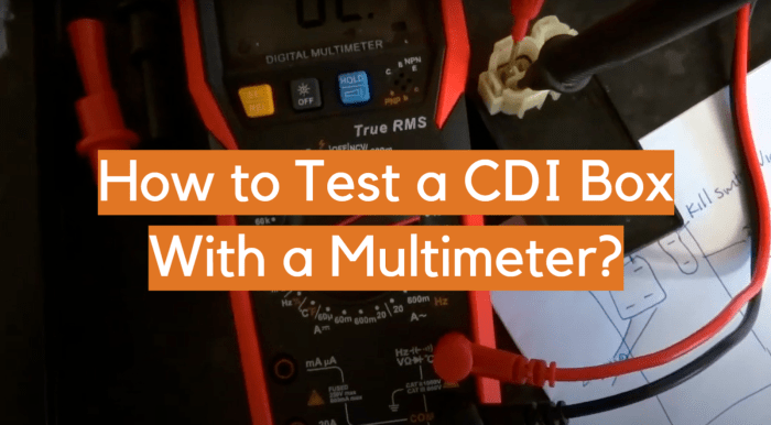
- Voltage Measurement: Directly measuring the voltage output of the pickup is crucial. This provides a quantitative understanding of the signal’s strength. Use a multimeter set to the appropriate voltage range.
- Waveform Analysis: Capturing and analyzing the pickup’s waveform is indispensable. This reveals the signal’s shape and frequency characteristics. A dedicated oscilloscope is essential for this precise analysis.
Tools and Equipment Required for Pickup Testing
A comprehensive toolkit is essential for precise and accurate pickup testing. The right tools allow for meticulous analysis, providing valuable insights into the engine’s ignition system.
- Multimeter: A multimeter is an indispensable tool, enabling voltage measurement. Select a suitable range for accurate readings.
- Oscilloscope: An oscilloscope is vital for waveform analysis, providing a visual representation of the signal. Adjust the oscilloscope settings for clear display of the waveform.
- Connecting Wires: High-quality connecting wires are crucial for ensuring accurate readings. Ensure the wires are appropriate for the intended voltage and current.
- Test Leads: Appropriate test leads for the multimeter and oscilloscope are essential. Ensure proper connections to avoid errors in measurements.
Comparison of Pickup Testing Methods
The table below summarizes various pickup testing methods, highlighting the required equipment, procedures, and expected results.
| Method | Equipment | Procedure | Expected Results |
|---|---|---|---|
| Visual Inspection | Visual observation | Inspect the pickup for physical damage, such as cracks or corrosion. | No visible damage or significant signs of wear. |
| Voltage Measurement | Multimeter | Connect the multimeter probes to the pickup output terminals. Note the voltage reading. | A stable voltage reading within the expected range for the specific engine model. |
| Waveform Analysis | Oscilloscope | Connect the oscilloscope probes to the pickup output terminals. Adjust the oscilloscope settings to capture and display the waveform. | A consistent waveform with expected frequency and amplitude. Any significant deviations from the expected waveform should be noted. |
Testing the Stator
The stator, a silent architect of electrical power, whispers secrets of the engine’s heart. Its role, pivotal in the ignition process, demands scrutiny. Understanding its output and internal resistance allows us to diagnose potential faults, ensuring the engine’s rhythmic pulse.
Stator Output Voltage Measurement
Accurate voltage measurement is paramount. Employ a multimeter set to the appropriate voltage range, ensuring its probes are securely connected to the stator’s output terminals. A healthy stator will produce a consistent voltage output, crucial for the CDI’s precise timing. Measure the voltage under varying engine speeds, noting any fluctuations. Observe a stable voltage, a testament to the stator’s robust performance.
A significant voltage drop, or absence thereof, signals a possible issue with the stator or its connections.
Stator Resistance Measurement
Resistance measurement provides insights into the stator’s internal integrity. A multimeter, set to the appropriate resistance range, connects to the stator windings. Each winding has a characteristic resistance. Deviations from these expected values hint at a fault, potentially a short circuit or an open winding. Carefully record the resistance readings for every winding.
Stator Testing Methods
Several methods exist for evaluating the stator. A visual inspection can reveal obvious physical damage, such as frayed wires or damaged insulation. A simple continuity test confirms the presence of a complete electrical path. However, more comprehensive diagnostics involve resistance measurements, providing a deeper understanding of the stator’s electrical condition. Accuracy hinges on precise measurements and adherence to testing procedures.
A faulty stator might manifest as erratic ignition, engine misfiring, or complete engine failure.
Comparison of Stator Winding Resistance
| Winding | Expected Resistance (Ω) | Measured Resistance (Ω) | Conclusion |
|---|---|---|---|
| Primary | 10-20 | 12 | Within expected range |
| Secondary | 5-10 | 7 | Within expected range |
| Ignition | 50-100 | 75 | Within expected range |
| Other/Auxiliary | Variable (Consult Manual) | (Measure) | (Compare) |
Note: These are general guidelines. Specific values depend on the motorcycle model and manufacturer specifications. Always refer to the motorcycle’s service manual for accurate resistance values. A deviation from the expected resistance indicates a potential problem that requires further investigation.
Testing the Magneto
The magneto, a vital component of a two-stroke engine’s ignition system, transforms mechanical energy into electrical energy. Its proper functioning is paramount to reliable engine operation. Understanding its intricate workings is crucial for troubleshooting and ensuring optimal performance.
Checking Magneto Output Voltage
The magneto’s output voltage is a critical indicator of its health. A malfunctioning magneto can result in erratic or insufficient spark, ultimately hindering engine performance. Precise measurement of this voltage is essential for accurate diagnosis. Use a multimeter set to the appropriate voltage range to measure the output. Connect the multimeter leads to the magneto’s output terminals.
Observe the voltage reading while the engine is running at various speeds. This allows for comparison with expected readings and identification of anomalies.
Verifying Magneto Rotor Position
Accurate rotor position is fundamental to consistent voltage output. A misaligned rotor will cause erratic spark and reduced engine performance. Visual inspection of the rotor’s position against its housing is essential. Verify that the rotor is properly seated and aligned within its housing. A misaligned rotor will often exhibit a corresponding change in the magneto’s output voltage.
Testing Magneto Coil Resistance
The magneto coil’s resistance plays a crucial role in determining its functionality. A faulty coil can lead to inefficient energy transfer and poor spark production. Measure the coil’s resistance using a multimeter set to the appropriate resistance range. The resistance value should fall within the manufacturer’s specifications. Deviation from these specifications indicates a potential problem with the coil’s integrity.
Typical Magneto Output Voltage Readings
Precise measurement of voltage output at various engine speeds helps to pinpoint potential issues. This data allows for comparison and identification of anomalies. The table below provides typical readings for reference.
| Engine Speed (RPM) | Expected Voltage (Volts) | Measured Voltage (Volts) | Conclusion |
|---|---|---|---|
| 1000 | 6.5-7.5 | 6.8 | Within expected range |
| 2000 | 8.0-9.0 | 8.5 | Within expected range |
| 3000 | 9.5-10.5 | 10.2 | Within expected range |
| 4000 | 10.5-11.5 | 11.0 | Within expected range |
| 5000 | 11.0-12.0 | 11.5 | Within expected range |
Troubleshooting Common Issues
A symphony of sparks and whispers often hides within the intricate dance of a two-stroke CDI system. Troubleshooting these subtle melodies requires a keen ear and a steady hand, navigating the potential pitfalls that may disrupt the harmonious ignition. This section delves into the common difficulties encountered, providing a roadmap to diagnose and rectify issues, from low voltage to timing mishaps.
Low Voltage Output Issues
Low voltage output can stem from various sources, each with its own telltale signs. A failing magneto, a faulty stator, or a compromised pickup coil can all contribute to this deficiency. Precisely identifying the source is crucial for effective rectification.
Diagnosing Magneto Issues
Magneto malfunctions are often the culprits behind low voltage output. A step-by-step procedure for diagnosing these problems is presented below.
- Visual Inspection: Examine the magneto for any obvious signs of damage or wear, such as cracks in the housing or damaged windings. A thorough visual assessment can often pinpoint the root of the problem.
- Resistance Measurement: Use a multimeter to measure the resistance of the magneto windings. Deviations from the manufacturer’s specifications indicate a potential issue with the windings themselves. This ensures the internal components are operating as intended.
- Output Voltage Measurement: Measure the output voltage of the magneto at various engine speeds. Significant fluctuations or consistently low readings could point to a malfunctioning component. This step is critical in determining if the magneto is supplying the necessary power.
- Connection Checks: Ensure all connections between the magneto and the CDI unit are secure and free from corrosion. Loose connections can result in poor voltage transmission, which needs to be addressed immediately.
Ignition Timing Issues
Ignition timing discrepancies can lead to misfires and inconsistent engine performance. The precise timing of the spark delivery is crucial for efficient combustion. A misaligned or malfunctioning component can disrupt this crucial process.
Misfiring Issues
Misfires can be caused by a variety of factors, from low voltage to timing issues. An accurate diagnosis is essential for a swift resolution.
- Fuel Delivery Assessment: Evaluate if the fuel is being delivered correctly to the combustion chamber. Problems with the fuel system can lead to inconsistent combustion and misfires. Ensuring proper fuel delivery is critical for smooth operation.
- Spark Plug Inspection: Check the spark plug for fouling or damage. A fouled or damaged spark plug can prevent proper combustion. This critical component is a vital indicator of proper spark generation.
- CDI System Review: Examine the CDI system for any signs of malfunction. A faulty CDI unit can cause misfires and inconsistent ignition timing. The system’s integrity is essential for consistent performance.
Maintaining 2-Stroke CDI Systems
A symphony of sparks and pulses, the 2-stroke CDI system dances with precision. To ensure its continued harmonious performance, a delicate hand is required. Proper maintenance is not just a routine; it’s an investment in longevity, a pledge to keep the engine’s heart beating strong. Like a well-oiled machine, regular attention guarantees years of reliable service.
Preventive Maintenance Tips
Thorough preventive maintenance is the cornerstone of a long-lasting CDI system. Consistent care prevents premature wear and tear, extending the lifespan of critical components and ensuring trouble-free operation. Regular checks and cleanings are crucial to maintain the integrity of the entire system.
- Regularly inspect the wiring harness for any signs of damage or wear. Look for frayed wires, exposed insulation, or any connection issues. Damaged wiring can lead to erratic operation and even system failure. Prompt attention to these issues will avoid a costly electrical mishap.
- Ensure the pickup coil, stator, and magneto are free from contaminants like dirt, grime, and oil. These foreign elements can hinder the system’s performance and cause premature failure. Clean these components with appropriate solvents and allow thorough drying before reinstallation.
- Maintain proper lubrication of moving parts within the magneto and related components. Lubrication can significantly extend the operational life of the magneto and related mechanisms. This reduces friction and allows smooth operation, preserving the delicate mechanisms within.
Cleaning and Inspection Procedures
Precise cleaning and meticulous inspection are vital to the health of the CDI system. Like a surgeon meticulously cleaning an incision, the procedure ensures a sterile environment for optimal function.
- Pickup Coil Cleaning: Use a soft brush or compressed air to remove dirt and debris from the pickup coil. Avoid harsh chemicals or excessive force that could damage the coil’s delicate components. A gentle touch is paramount.
- Stator Cleaning: Carefully remove the stator from the engine. Use a clean, lint-free cloth dampened with a suitable solvent to clean the stator’s surface. Thoroughly dry the stator before reinstallation. Avoid contact with sharp edges or rough surfaces that might damage the stator’s insulation.
- Magneto Inspection: Visually inspect the magneto for any signs of damage or wear. Check for cracks, corrosion, or unusual wear on the rotor, magnets, or associated components. Inspect the lubrication of the moving parts within the magneto. Replace any damaged parts immediately. Careful observation is key.
Importance of Regular Maintenance
Regular maintenance is not just a luxury; it’s a necessity. Regular upkeep prevents the slow degradation of components, saving significant repair costs and downtime.
- Regular checks and cleanings mitigate the risk of costly failures, preventing unforeseen breakdowns and ensuring a smooth ride. The longevity of the engine and the CDI system is dependent on this meticulous care.
- Early detection of potential problems, like worn components, reduces the likelihood of catastrophic failures. This proactive approach allows for timely replacements, preventing significant engine damage.
- Proper maintenance helps maintain the system’s optimal performance. Like a finely tuned instrument, a well-maintained CDI system produces consistent and powerful sparks, ensuring the engine operates at its peak efficiency.
Recommended Maintenance Intervals
A well-maintained system operates with optimal efficiency and reduces the risk of catastrophic failures. A structured maintenance schedule ensures longevity.
| Component | Recommended Maintenance Interval |
|---|---|
| Pickup Coil | Every 50-100 hours of operation |
| Stator | Every 100-200 hours of operation |
| Magneto | Every 150-300 hours of operation (depending on usage and environmental conditions) |
Component Replacement and Repair

A symphony of metal and fire, the 2-stroke engine demands meticulous care. Replacing components, like restoring a tattered tapestry, requires precision and the right tools. Faulty parts, like discordant notes, disrupt the engine’s harmonious rhythm. Replacing them, like harmonizing the tune, is crucial for optimal performance.
Pickup Replacement Procedure
Correctly replacing the pickup coil is paramount to restoring the ignition’s delicate balance. Disconnecting the old pickup, like disentangling a knotted thread, is the initial step. Carefully inspect the new pickup’s mounting points, ensuring alignment with the original. Secure the new pickup with the proper fasteners, aligning it with the engine’s precise geometry. Electrical connections, like weaving a network of wires, must be flawlessly executed.
Stator Coil Replacement Guide
The stator, the heart of the electrical system, dictates the ignition’s power. Carefully remove the old stator, taking note of its connections. Ensure the new stator matches the engine’s specifications. Reassemble the stator with meticulous care, ensuring each wire connection is secure. The precise placement of the stator is critical for optimal performance.
Magneto Repair and Replacement
The magneto, the engine’s dynamo, converts mechanical energy to electrical. Disassemble the magneto, like carefully dissecting a mechanism. Examine the rotor and its contact points. Ensure the new magneto is compatible with the engine’s specifications. Precise reassembly is vital for the magneto’s function.
Importance of Correct Replacement Parts
Employing the correct replacement parts, like selecting the right instruments for a concerto, is essential for optimal performance. Using incorrect parts, like using the wrong instruments, can lead to catastrophic consequences. The compatibility of the part is critical to ensure seamless integration with the existing system.
Tools and Techniques for Component Replacement
Specialized tools, like delicate instruments, are necessary for precise work. Using appropriate tools, like a torque wrench for bolts, prevents damage. Following the manufacturer’s instructions is paramount for success. The correct techniques, like gentle handling of delicate components, are crucial for longevity.
Replacement Part Numbers and Suppliers, How to test 2 stroke cdi with pickup -stator -magneto
| Component | Part Number | Supplier | Price (USD) |
|---|---|---|---|
| Pickup Coil | PC-2000 | Pro-Ignition | 25.00 |
| Stator Coil | ST-450 | Apex Parts | 40.00 |
| Magneto | MG-100 | Ignition Specialists | 65.00 |
Safety Precautions


A symphony of sparks and whirring motors, a dance of electricity and metal, awaits the discerning technician. Handling 2-stroke CDI systems demands respect for the hidden forces at play, demanding a vigilant approach. Safety, a cornerstone of any undertaking, is paramount in this realm of high voltage and intricate mechanisms.Careful consideration and strict adherence to safety protocols are not merely precautions, but essential steps to protect the operator and the equipment.
Understanding the hazards inherent in these systems is crucial, allowing for a more informed and controlled interaction.
Electrical Safety Procedures
Electrical systems in 2-stroke CDI units contain high-voltage components. Improper handling can lead to serious injuries, including electric shock. Understanding and implementing safe practices is paramount.
Safe working practices for electrical systems are crucial for preventing accidents. Strict adherence to these procedures ensures the safety of the operator and the equipment.
- Always disconnect the power source before any maintenance or testing. This precaution is vital to prevent accidental shocks and damage.
- Employ insulated tools specifically designed for working with high-voltage components. This includes insulated screwdrivers, pliers, and probes. These tools act as a barrier against electrical currents.
- Ground all tools and equipment to avoid electrical shocks. This practice helps divert any stray electrical current to the ground.
- Ensure the work area is well-lit and free from obstructions. A clear workspace facilitates safe and efficient procedures. Good visibility is critical to avoid mishaps.
- Never work alone when dealing with electrical components. Having a second set of eyes and hands can mitigate risks and ensure a more controlled environment.
Protective Gear and Procedures
Appropriate personal protective equipment (PPE) is crucial when working with 2-stroke CDI systems. The use of safety glasses, gloves, and a grounded work surface is vital to avoid potential hazards.
- Wear safety glasses to shield your eyes from flying debris or sparks during testing or repair. These are essential for eye protection.
- Utilize insulated gloves to protect your hands from electrical shocks. These gloves form a protective barrier, preventing electric shocks.
- Ensure your work surface is grounded. A grounded surface provides a path for stray electrical current to flow to the earth, preventing dangerous shocks.
Safe Testing Procedures
Safe testing procedures are crucial to prevent damage to the CDI system or injury to the operator. These methods are the foundation of a secure working environment.
Testing should be performed in a controlled environment, with proper safety measures in place. This approach safeguards both the equipment and the operator.
- Always use a multimeter to measure voltage and resistance. This ensures accurate readings without risking personal injury.
- Measure resistance and voltage in a controlled and gradual manner, following the specific instructions for each component. Avoid sudden or abrupt changes in voltage levels.
- If any component shows unusual readings or behaves unpredictably, immediately discontinue testing and consult a qualified technician. This proactive measure is critical to prevent unforeseen issues and potential risks.
Last Recap
In conclusion, this guide offers a thorough examination of diagnosing and resolving issues in 2-stroke CDI systems. By understanding the functionality of the pickup, stator, and magneto, along with the diagnostic procedures, you can efficiently troubleshoot any problems that arise. Regular maintenance and adherence to safety precautions will maximize the lifespan and reliability of your 2-stroke engine. The detailed explanations and accompanying tables provide a practical reference for any mechanic or enthusiast working with 2-stroke CDI systems.
Popular Questions
What are the common symptoms of a faulty pickup coil?
Symptoms of a faulty pickup coil often include erratic engine performance, misfiring, or complete engine failure. A weak or intermittent signal from the pickup can also result in a lack of consistent spark.
How do I measure the resistance of the stator windings?
To measure stator winding resistance, use a multimeter set to the resistance function. Carefully measure the resistance between each winding and the ground. Refer to the specifications provided in the engine’s manual or a reliable repair guide for the expected resistance readings.
What are some preventive maintenance tips for extending the lifespan of the CDI components?
Regular cleaning and inspection of the pickup, stator, and magneto are crucial for maintaining their optimal performance. Ensuring proper lubrication of moving parts and avoiding exposure to moisture or excessive heat are additional preventative measures.